Monday 10 December 2012

How Does LED Emits Various Color ??

LED (Light Emitting Diode)

We have learned about LED's construction, circuit pinout in our post on LED's (click here).

In this post we are going to discuss about the color of the LED, many few of us know "How LED emits color light".


  • The color of the emitted light is decided by its wavelength.
  • As we know LED's are made up of semiconductor material, hence the "color of the LED depends upon the the material used to made LED."
  •  Silicon and Germanium are not used because the do not emit light in the visible spectrum.

  • Colors associated with the different materials are as follows

  • RED OR YELLOW            --- Gallium Arsenide Phosphide (Ga As P) is used.
  • RED OR GREEN               --- Gallium Phospide (Ga P) is used.
  • Infrared                                --- Gallium Arsenide (Ga As) is used.
  • Blue                                       --- Galium Nitride (Ga N) is used.

  • Some LED's are capable of emitting infrared light which is not visible to our eyes.
Continue Reading ...

Tuesday 17 July 2012

Introduction to Diode

Diode is a two terminal electrical component i.e. anode and cathode. Diode is the first semiconductor electronic component, it is an very important component in electronics, we can say that  " Diode is the Heart of Electronics".
Types of Diode include Rectifier diode(normal diode), Zener diode, Signal diode, Light emitting Diode etc.


Continue Reading ...

Thursday 28 June 2012

How To Make PCB at Home

"How to make PCB at home ?" is always an question in front of all electronics hobbyist. Here i will teach you most common method used at home for making PCB, known as "Toner Transfer Method". It is a very easy and cheap process of making a PCB at home.

Here is the list of all the things you will be going to need to make an PCB
 1. Copper PCB board.
2. A photo paper (also known as glossy paper).
3. Ferric Chloride FeCl2 solution. (Substitute for ferric cholride : The mixture of HCl acid and Hydrogen  Peroxide, in the proportion 1:2 i.e one parts of HCl and two part of hydrogen Peroxide)
4. Plastic container.
5. Electrical or Masking tape.
6. Electric Iron.
7. Acetone.
8. Drill

Continue Reading ...

Saturday 9 June 2012

5 Awesome Notepad Tricks

1. Cycle a message in your friend's computer:
Type :

@ECHO off
:Begin
msg * Hi
msg * Are you having fun?
msg * I am!
msg * Lets have fun together!
msg * Because you have been o-w-n-e-d
GOTO BEGIN


Save it as Anything.BAT and give it to your friend. You can change the message and type your own message there.
 

Continue Reading ...

Monday 23 April 2012

How To Enable And Disable USB Port Of Your PC

In this post i will show you how to disable all the USB ports of your PC. After disabling this USB ports you cannot use any of the USB device om your PC. This trick will also help you to protect your PC data from an external threat.

As this trick is an Registry trick i recommend you to Backup your Registry, if you are unaware of how to backup the registry, please click here to learn "How To Backup The Registry"

Thus there is no problem trying this trick on your PC, as i have also shown the trick to enable the USB ports but don't forget to Backup the Registry.
Let's get this job done.
  • Click on START and then on RUN.
  • Type REGEDIT in the dialogue box and press Enter.
  • Now go to the following address,  HKEY_LOCAL_MACHINE\SYSTEM\CurrentControlSet\Services\USBSTOR.
  • Search for the "START" key in the right side column, and double click on it.
  • Change its Value Data from "3" to "4", now its done just close the registry and restart your PC.
  • Check that all your USB ports are disabled.
  • Now to re-enable the USB port just change the value data from "4" to "3" again
If you like this post don't forget to share it with your friends, and also Subscribe to our free email Subscription.
Continue Reading ...

Sunday 11 March 2012

Electronic Reference Book

Electronic reference book is a very good medium of knowledge for electronics student, it covers many basic topics such as Equations for solving electronics problem, troubleshooting, designing and manyother useful content.


License : Free

Size : 838 kb

Click here to Download
Continue Reading ...

Saturday 3 March 2012

How To Hide The Shutdown Button In XP

Hide Shutdown button trick is based on registry, in this trick i am going to show you how to vanish the shutdown button in just seconds.
You can use this trick to fool or surprise anybody, you can bet your friends to shutdown your pc.

As i say this is an Registry trick, so i prefer you to backup the registry before you mess it up.
click here to learn How to Backup the registry

  • The first thing you have to do is you must log into the Administrative Rights.
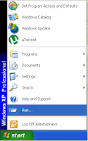
  • Now Click Start button click on "Run", Dialogue box will open.
  • Type "regedit" and press enter to open the Regedit editor.
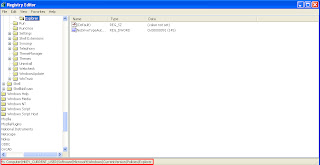
  • Now explore to the address : HKEY_CURRENT_USER\Software\Microsoft\Windows\CurrentVersion \Policies\Explorer.
 
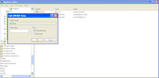
  • Now in the right side window, right click and create new DWORD value, and name it "NoClose" (Since the words are case sensitive, you must type as it is).
  • After renaming right click on it and click on modify, and assign value 1 to its value data box.
 
  • Now close the Registry and Restart the system, because after editing Registry you need to restart the system every time.
  • After restarting try to shutdown your pc, you will find that Shutdown button have been vanished.

  • I bet you can't shutdown without reading the solution.
  • Now again open the registry editor and repeat step 4.
  • Right click on "NoClose" and click on modify, now assign value 0 to its value data box.
  • But still in registry, for any changes to go into effect you must restart the system, so how can you restart now.
  • Well i still have the solution, the only way to shutdown your pc while trick is working.
  • Go to start menu and log off your pc, there will be "Turn Off" option on the lower left side corner.

So enjoy the trick and if you like it don't forget to share. And also Subscribe to our free email subscription.

If any doubt please let me know..
Continue Reading ...

Thursday 1 March 2012

Neutrino Travels Faster Than Light ! ! !

Neutrino is a particle which exist everywhere on earth in plenty,  it is said that about millions of neutrinos passed us every second's. But we can't feel them, neither sea them with our naked eyes.

Neutrino is very tiny in size and it is described as weightless with no electric charge. Its size is described by giving an example of atom i.e., "If atom is the Solar system then neutrino is the golf ball in that Solar system."

This small little tiny Neutrino is capable of travelling through a solid matter, without reacting with anything.

Our great scientist Einstein's theory says that " The speed of the in vacuum is very high, and no other thing with mass can travel faster than light."


But the research says that there is a possibility that Neutrinos are faster than light. Thus it is not been totally accepted, as more research is needed to prove that Neutrino are faster than light.

But if this sentence is true then the world is going to turn upside down, as our many theory are depending Einstein's theory of light, and their will be a situation where we would have to tear all our textbooks and rewrite them.

Another theory says that if you travels faster than speed of the light you might end up in the future, so if this Neutrino are really faster than light than they might help us to Time travel.

So you can imagine What next to come? if neutrino are faster than light.
Continue Reading ...

Wednesday 29 February 2012

Solar Paint That Generate Electricity

Today the technology is moving on the Express Highway, it is growing in such a way that it has made the word "IMPOSSIBLE" to say "I M POSSIBLE".
Have you ever imagined a paint that generate a electricity, a paint that will power our house hold appliances?.

Yes! the paint that work as a solar cell, generating electricity by using sunlight is going to come into action soon.

At University of Notre Dame in U.S.A., a team of researchers leaded by Professor Prashant Kamat has created this solar paint. The paint uses semiconducting nano particles to produce energy.

Professor Prashant Kamat said "By incorporating power-producing nanoparticles, called quantum dots, into a spreadable compound, we've made a one-coat solar paint that can be applied to any conductive surface without special equipment."

How It Is Made?
Titanium dioxide (nano sized particles) is coated with either cadmium selenide or cadmium sulphide, this particles are then suspended in a water-alcohol mixture to create a paste, this paste is nothing but the solar paint. The generated paste is then applied on a transparent conducting material, now if this material is exposed to light it literally generate electricity.

Advantages Over Traditional Solar Cells
1)Photovoltaic paint has a number of advantages over traditional solar cells such as, it doesn’t have the material limitations of silicon solar cells, so it theoretically provides many terawatts of electricity at a low cost.
2)The paint can absorb light across the visible spectrum, so even cloudy days will reap lots of energy.
3)It can be available in low cost then solar cell

Thus we know what electricity means to us now and in future, nowadays many of us use solar cell inorder to conserve our limited resources. Thus this solar paint has many advantages over solar cell and it can be a acceleration point in the field of conservation of resources, so let's hope for the best.
Continue Reading ...

Tuesday 28 February 2012

NE555 Timer IC

NE555 is an Timer IC in DIP (Dual Inline Package). It was designed by Hans Camenzind in 1970.
It is an integrated circuit used in variety of Timers, Oscillators and Pulse generation operation.
It was brought into market by Signetics. in 1971, later than it was acquired by Philips. It was also known by the name Time Machine at that time.

Depending on the manufacturer the IC contains about 20 Transistor, 2 Diode, and 15 Resistor installed on a silicon chip in an 8-pin DIP.

There is also other two IC's called 556 and 558. 556 IC is a 14-pin DIP and it is a combination of two 555 IC, and 558 is a 16-pin Dip with the combination of four 555 IC.

555 IC Pinouts


1) GND (Ground) : It is connected to the ground of the circuit.
2) TRIG (Trigger) : It is the trigger point at which when the input falls below 1/3 of the Vcc, the output rises and the Pulse start (Interval starts).
3) OUT (Output) : It is the output point from where the IC gives the output.
4) RESET : It is a reset point from where we can set the timing interval by connecting it to the ground.
5) CTRL (Control) : It is an control point from where we can access the Internal Voltage Divider of the IC. Internal Voltage Divider function divide the Vcc into 2/3.
6) THR (Threshold) : When the input at THR is greater than CTRL then the inteval comes to an end.
7) DIS (Discharge) : It may be used to discharge a capacitor between the interval.
8) Vcc : It is the Vcc point of the IC where input voltage to the IC is supplied, input voltage of the IC is between 3v-5v.

Looking further this IC has three operating modes:
1) Monostable mode : The monostable operation mode is a circuit that produces an output pulse of fixed duration each time the input circuit is triggered. Taking an example of an LED, if we want any LED to glow for a specific time and then switch off then we should use Monostable mode circuit.
Its other application include touch switches, frequency divider, missing pulse detection, etc.
2) Astable mode : In Astable mode the circuit produces an output pulse of fixed duration and continuously produces that pulse once triggered.
Other application include lamp flasher, security alarm, tone generation, logic clocks,etc.
3) Bistable mobe : This is also known as Schmitt trigger,in this mode 555 can operate as a flip-flop. It's uses include latch free switches.
Continue Reading ...

Sunday 26 February 2012

IC LM78XX for Power supply

The 78XX series is the series of voltage regulator IC's, this series of IC's are mostly used in power supply circuit. Due to its some advantages and low cost it is widely used .

In this series of 78XX ,"XX" is replaced by 2 digit depending on its output voltage. Such as 7805 (5 volts), 7806 (6 volts), 7809 (9 volts), 7812 (12 volts), 7815 (15 volts), 7818 (18 volts), 7824 (24 volts).


The IC consists of three terminals:
  1. Input (Line voltage).
  2. Ground(Common).
  3. Output (VReg).
This IC consist of a heatsink, which help it from damaging through heat.
But if the current is more than the IC will get heated very fast, the solution is to join another heatsink to the IC .


I have posted some power supply project based this IC, click here (for 5v power supply circuit)
Continue Reading ...

Simple 5V Power Supply Circuit

A simple 5V power supply circuit, consisting of few components which can be found very easily. I will explain you the step by step guide to build this power supply.

First of all you need to gather some component given below :
  1. T1 :0v-24v Transformer (you can also used 12v transformer)
  2. D1, D2, D3, D4 : 1N4007
  3. C2 :1000uF
  4. C3 :100uF
  5. IC : LM7805
I have gathered all the component from the faulty power supplies. Most of the power supply consist of IC LM7805, if you do not find you can buy it.
So Here is the circuit for you,


The circuit above takes the input of 240vAC and gives the output of 12vDC.

This 240 VAC is brought down by a step down transformer upto 24vAC, this AC current is then rectified using Bridge rectifier, (to know how rectifier convert AC to DC click here).

After the rectification, we need to get the current ripple free for that purpose we use 1000uF capacitor C2 (C1 is not their in the circuit above).
Now the thing we need is regulated 5V DC, IC LM7805 does this job.
It directly gives us the output of 5V.
To know more about 78XX series click here (must read it's important)

But the important thing is the current, this circuit gives about 1A,use resistor in series with the load if the current rating of your load is low.

Enjoy the circuit, if any question don't hesitate to comment.

You can subscribe our free email subscription for the updates, also you can share this post on social networking sites by clicking on the respective icons.
Continue Reading ...

Saturday 11 February 2012

Radiation from Laptop

In my last post about TIPS TO AVOID MOBILE RADIATION, i have discussed ill effect of radiation on living being and also discussed tips to avoid radiation from mobile phones.
Thus my readers have asked me to post about the radiation through laptop without Wi-Fi.

Thus we know Wi-Fi, it help us to connect through the wireless network any time any where. But still it has its disadvantages where Radiation is considered.
When we talk about the radiation through Laptop without Wi-Fi, some of us may think that there is no radiation from laptop without Wi-Fi, but it is.
The point the Radiation from the Laptop is in very small proportion that we considered as it is negligible.And it does not harm us in large proportion.

Lets get back to the Wi-Fi topic, as i discussed in my earlier post Wi-Fi radiation may also be giving us more infertility by decreasing sperm motility and damaging DNA in sperm.

Electromagnetic radiation is a product of wireless communication, and researchers suggest this radiation may be causing sperm damage. "We speculate that keeping a laptop connected wirelessly to the internet on the lap near the testes may result in decreased male fertility." says researchers.

Thus the solution for this is keep the laptop off your lap, or you can also keep it on your desk.

I suggest you to use wired connection when possible, because every wireless connection may emit Radiations.
Continue Reading ...

Friday 10 February 2012

Tips to avoid Mobile Radiation

Radiation is a process in which energetic waves travels through a medium from one position to another. Radiation occurs when an unstable nuclei of atom decay and release particles. When these particles touches various organic matter such as damage is done. Radiation can cause cancer, burns, and also deaths.

Well according to me today Radiation is more hazardous than smoking.

Mobile are not the only cause of Radiation, but Wi-Fi, laptops, etc also causes Radiation. But the usage of mobile phone has been increased resulting in the increase in Radiation level. Hence it has to be looked urgently.


Radiation not only effect human being but it also effect other living being. Due to the Radiation birds lost their direction when they approached the antenna and start flying in zigzag direction. Earlier radiation was less, but today due to the increase in the use of mobile phones and as most of the individual has mobile phone, every individual act as an source of an Radiation.

The most common effect of Radiation on human being are,
  1. Headache
  2. Hair loss
  3. It damages to WBC (White Blood Cells)
  4. It damages our nerve cells
  5. Lack of concentration
Yet this is not the end there are hundreds of effect. So try to avoid Radiation as possible.

Tips to avoid Radiation
  1. Buy cellphones with low SAR ratings.
  2. Minimise the time you speak on your mobile phone.
  3. Avoid calling when Battery is low or when Signal is weak because at that time our mobile radiates maximum.
  4. Keep your phone as far away from your body.
  5. Keep the phone away while sleeping.
  6. Avoid putting the phone in your left pocket as it is closer to your Heart.
  7. Don't clipped your phone to your belt, as it affect the fertility.
  8. Keep switching the phone to your left and right side of your head while talking.
  9. Pregnant woman should avoid cellphones as it affect the foetus.
  10. Avoid unwanted calls and advertisement.
  11. Use landline connection.
  12. Keep childrens away from the cellphone as they are more susceptible to cell damage.
(This point has been taken from efy magazine)

As i say childrens should be kept away from the cellphones because, they are the one who are using it from their childhood. The study says that if a person body having exposure to cellphone for 10 years may have started to built a tumor in their body.
Continue Reading ...

Sunday 15 January 2012

Working of Diodes

A diode is a specialised electronic component with two electrodes called the anode and the cathode.
 A diode allows current to flow in only ONE direction. If the cathode end (marked with a silver stripe) is connected to the negative and anode is connected to positive then current will flow.
A diode has a forward voltage drop. That means, when current is flowing, the voltage at the anode is always higher than the voltage at the cathode.

 The actual Forward Voltage Drop varies according to the type of diode.
For example: Silicon diode = 0.6 to 0.7v (depending on type) 
                     Schottky diode = 0.3v 
                     Germanium diode = 0.2v


In addition, the voltage drop increases slightly as the current increases so, for example, a silicon rectifier diode might have a forward voltage drop of 0.7v when 100mA is flowing but 1.0 volt when 1 Amp is flowing.


A ZENER diode does not allow current to flow until the voltage on its cathode reaches a value called the "Zener Voltage." At this voltage the diode "breaks down" and a LOT of current will flow and must be restricted by connecting a resistor in series. At this point the supply voltage can increase and the voltage across the zener will remain constant. Values of 2.4 volts to 100 volts or more are common. Zener diodes are used to "clamp" a voltage in order to prevent it rising higher than a certain value. This might be to protect a circuit from damage. Zener diodes are also used to provide a fixed "reference voltage" from a supply that varies. They are widely used in regulated power supply circuits. 


TO KNOW MORE ABOUT ZENER DIODE CLICK HERE
Continue Reading ...

Saturday 14 January 2012

Introduction to AC and DC

We know that battery or cell gives DC (Direct current) with steady voltage.It is used to power electronics application such as Televisions, mobiles etc.
DC has steady waveform, that is a straight line you can observe it in the below graphical diagram.
DC waveform

Whereas AC means Alternating Current, which means it alternately rises and fall from it highest
positive value to its lowest value. Thus it form a sinusoidal wave in the graphical diagram.
AC sinusoidal waveform
Thus it is important to understand between AC and DC, we cannot connect a 12V application directly to the to the AC that is main power supply it can be hazardous, thus depending upon the countries 110V AC or 230V AC is supplied to us for household application.

Production of AC and DC
In a power station, electricity can be made most easily by using a gas or steam turbine or water impeller to drive a generator consisting of a magnet spinning inside a set of coils. The resultant voltage is always "alternating" by virtue of the magnet's rotation you can observe it in the above AC sinusoidal waveform diagram how the voltage rises positive then goes negative. This alternating voltage can be carried around the country via cables far more effectively than direct current because AC can be passed through a transformer and a high voltage can be reduced to a low voltage, suitable for use in homes.
This DC is produced by several procedure such as Transformation, Rectification, etc.
DC Conversion
The electricity arrives at your house is alternating voltage. Electric light bulbs and toasters can operate perfectly from 230 volts AC. Other equipment such as televisions have an internal power supply which converts the 230 volts AC to a low DC voltage for the electronic circuits. How is this done? There are several ways but the simplest is to use a transformer to reduce the voltage to, say 12 volts AC (above figure of DC conversion). This lower voltage can be fed through a "Rectifier" which combines the negative and positive alternating cycles so that only positive cycles emerge.
TO KNOW MORE ABOUT RECTIFIER CLICK HERE
DC waveform of full wave rectifier
This "rectified" voltage is suitable for powering things like filament bulbs and electric trains but it is still no good for electronic circuits. What we need is "regulated DC" which truly simulates the steady voltage you get from a battery (cell). The first step is to connect a large value capacitor to the output of the rectifier. A capacitor acts as a voltage reservoir and has the effect of smoothing the "ripples".
Rectified waveform (smoothing the ripples)
But the output is still not the same as a battery but it's often good enough for charging batteries in mobile phones, but if you connect it to stereo equipment, you will hear the ripple as an annoying background hum. The final step is to pass this "rippling DC" through a regulator unit. This effectively reduces the ripple to leave almost pure "regulated DC" suitable for powering electronics equipment such as stereos.
Regulated DC power supply
A high-quality Regulated Power supply is capable of supplying 1.5 Amps (1,500 milliamps) of current. A rotary switch provides selection of 3, 4.5, 6, 7.5, 9 or 12 volts "regulated d.c." It has a multitude of uses, including speed control for a mini drill, amplifiers, CD players etc.
Continue Reading ...

Monday 2 January 2012

Surface Mount Device (SMD)

Surface Mount Device/components are very small as compared to normal electronics components like resistor, capacitor etc.Surface Mount Device is specially designed for the integration of the circuit i.e to make the circuit as small as possible. Integrated Circuit (IC) is the example of the SMD components, if you open datasheet of any IC you can see the circuit diagram of that particular IC, thus we can see the result of application of SMD components in electronic circuit.


You must have seen the above figure of SMD components, they are so minute that you will need magnifying
glass in order to read there values.
If you are interested to know how to read SMD components like Resistor, Capacitor etc. then click on the below link.
How To Read SMD Resistor.
How To Read SMD Capacitor.

Thus we have seen the size of the SMD components, while reading you must have been thinking about how to solder them or how are they soldered on pcb. Below explained are two methods of soldering surface mount devices.

METHOD 1 :
Surface Mount Device are soldered by automatic placement (by Robots) onto a specially designed board. This device are placed on the board and thus held on the board using glue. This board is then exposed to an high temperature air, thus the small amount of solder on the board is sufficient to make the solder connection on each of the pins of the surface mount device. The solder on each of the point is melted and forms a bond with the leads of the component. This method is known as re-flow.


METHOD 2 : Another method of soldering SMD components is by shallow bath of molten solder. The parts are glued in place and then the board is turned over and placed above the solder and a wave is created that just touches the board and at the same time deposits a small amount of solder on each of the points. Surface-mount components are designed to withstand a 10 second immersion during the soldering process.This point is mentioned in order to let you know that the temperature of the solder bath is strictly controlled and the solder-time is kept to a minimum.
 

While in case of an average hobbyist you will be needing three major items,
1. Fine tweezers
2. Very fine tipped soldering iron with adjustable temperature.
3.Fine solder (very very fine).
4.Magnifying glass lamp to help with placement, soldering and inspection.


If you are going to solder your first SMD components i suggest you to first practice desoldering and soldering on a scrap printed circuit board.(Nowadays many electronic items are been made using SMD components, hence you can find them easily.)
Continue Reading ...

How To Read SMD Capacitor

Surface Mount Capacitor
Surface mount capacitor are usually of brownish or yellowish colour, from the colour one can identify whether given component is capacitor to some extent.


But Most SM capacitors values are not identified in any way by visualising ,most of them think that they are identified according to there size but SIZE OF THE COMPONENTS DOES NOT INDICATE THE CAPACITANCE as each capacitor has a different number of layers according to there manufacturer.

The only way to "read" the value of these SM capacitor is via a capacitance meter.

But some of the SM capacitor has number on there surface as that of SM resistor (A three digit number or alphabets).


Similarly as SM resistor there values are indicated, i.e if the number is 107 then first two digit are the answer and the third digit is the number of zero's.
107 = 10 (two numbers) 0000000 (seven zero's)
These value of capacitor is given in pf, hence the value is 100000000pf = 100uf (100 microfarad).
Continue Reading ...

How To Read SMD Resistor

We have discussed about SMD component in our last post SURFACE MOUNT DEVICE.
So in this post we are going to discussed about SMD Resistor and to find the value of resistor from the printed numerical code on its surface.
Above image has six SMD Resistor, now first of all how can you find whether the given component is resistor or an capacitor.
The answer is from the color of the component, SMD resistor are in black color with resistance printed on there surface.

Now, the resistors in the above image has 3 digit code (some resistor has 4 digit code also).

The code is 103, so the first two digit represent the answer and the last digit represent the number of zero's should be added after the answer.
Example :
103 = 10 (the two number) 000 (three zero's).
Hence the final answer is 10000 Ohms (answer obtain is always in ohms, further we can convert it).
Here are some more example 
334 = 330 000Ohms = 330k
443 = 44 000Ohms = 44k

Now, you can see the above component with code 2512.i.e it has the four digit color coding, the value of this resistor is decoded in the same manner.
The resistor with the value below 10 ohms has letter "R" to denote the position of the decimal point.
Such as 5.7Ω can be written as 5R7
6.2Ω =6R2
2.2Ω =2R2

Continue Reading ...
x

Get Our Latest Posts Via Email - It's Free

Enter your email address:

Delivered by FeedBurner